Mini-Review: Solder Party's RP2350 boards
Solder Party is a Swedish company that has some peculiar boards. For the RP2350 (and RP2040), they have stamp boards, which contain the microcontroller, and carrier boards, where the stamps are connected and provide power and input/output connectors.
One detail that will bother many people is that the pin spacing on the stamp boards is 2 mm instead of the more traditional 0.1" (2.54 mm). SolderParty sells connectors with this spacing.
Although some carriers have RP2040 in their names, all models work with RP2040 and RP2350 stamps.
I purchased both stamp models with RP2350 and the three carrier models. Here are some comments on them.
 |
| The RP2350 Stamp XL installed into the RP2xxx Stamp Carrier XL |
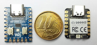
RP2350 Stamp

This is a small board, measuring 1" by 1". Along a RP2350A, it contains quite a lot of stuff:
- 16M of Flash
- LDO voltage regulator, supplying 3.3V @ 500mA
- LIPO battery support, including charging
- Boot and Reset buttons
- 12MHz crystal
The pins on the edge include the 30 GPIO pins, USB, power, and SWD. The pinout is the same as the RP2040 model.
RP2350 Stamp XL

- Has pads for the standard Raspberry Pi connectors for SWD (debug) and UART
- Space to solder a second Flash or PSRAM
RP2040 Stamp Carrier

The stamp (RP2040 or RP2350) can be connected by direct soldering or using connectors with 2 mm spacing.
The board follows the format and pinout of the Uno R3, but with pins working at 3.3 V. It has:
- Boot and Reset buttons at the edges
- USB-C connector
- Power barrel connector (7 to 12 VDC)
- Connector (non-standard) for SWD
- Connector for LIPO battery
- LED
- Standard Qwiic I2C connector
The through-hole connectors are supplied with the board, but not soldered.
RP2040 Stamp Round Carrier

The Round Carrier is, as the name suggests, a circular board containing 16 WS2812B RGB LEDs. The stamp (RP2040 or RP2350) can be connected by direct soldering, using connectors with 2 mm spacing, or using FlexyPins (which I will describe later).
The board has holes on the edge for connection using alligator clips and:
- A USB-C connector
- One normal LED
- A on/off switch
- A LIPO battery connector
- Two user buttons
RP2xxx Stamp Carrier XL
This model is the only one that supports the RP2350 Stamp XL. It can also be used with the RP2040 and RP2350 Stamps, but then several pins will be disconnected. The stamp connection can be made by direct soldering, using connectors with 2 mm spacing, or using FlexyPins.
The board has the dimensions of the Arduino Mega/Due, but with pins working at 3.3V and without the double row of pins on the opposite end to the USB connector. It has:
- Boot and Reset buttons
- USB-C and USB-A connectors
- A power barrel connector (7 to 12 VDC)
- A micro SD card socket
- Standard Raspberry Pi connectors for SWD (debug) and UART
- A LIPO battery connector
- One normal LED
- Two user buttons
- A standard Qwiic I2C connector
- A micro HDMI connector for use with the RP2350 HSTX peripheral
The through-hole connectors are supplied with the board, but not soldered.
FlexyPin


Comments
Post a Comment