Using the PIO to Interface a PS/2 Keyboard
One of the most intriguing features of the RP2040 used in the Raspberry Pi Pico is the PIO - Programmable Input/Output. It allows us to execute small programs that handle digital input and output independently to the ARM Cortex M0+ Cores.
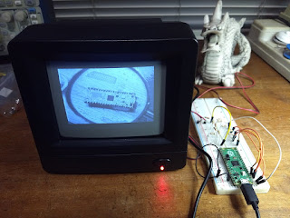
For my first study of the PIO I decided to interface a PS/2 keyboard. In the past I have interfaced one of these keyboards to a Arduino Nano, reading the bits one by one in an interrupt generated by the clock signal. Using the PIO, the main processor will receive a complete byte in one go.
 |
| An old but working PS/2 keyboard |

The figure bellow shows the pinout of the PS/2 connector:

- The RP2040 has two PIO blocks
- Each PIO block has four independently running state machines.
- Each PIO block has a program memory, shared by the four state machines, with room for 32 PIO instructions.
Each PIO state machine has:
- Two 32 bit shift registers
- Access to all 30 GPIO pins for digital input and output (four of these bits are used for connecting the Flash memory and should not be messed)
- Access to two 32 bits, four position, queues for bidirectional communication with the ARM cores. and DMA. If you are communicating only in one direction, you can reconfigure them to a single 8 position queue.
There are only nine PIO instructions: JMP, WAIT, IN, OUT, PUSH, PULL, MOV, IRQ, e SET. Writing a program from scratch can be daunting. Thankfully the Raspberry Foundation gives many examples in https://github.com/raspberrypi/pico-examples/tree/master/pio.
In our case the can start from the "clocked input" example: reading bits signaled by clock pulses. In this example the PIO program has only three instructions (wrap_target and wrap affect the configuration):
    wrap_target()
    wait 0 pin 1
    wait 1 pin 1
    in pins, 1
    wrap()
- The rest state for the clock is high, the data is sampled in the falling edge
- We have a total of 11 bits
import time
import rp2
from machine import Pin

# in_shiftdir=rp2.PIO.SHIFT_RIGHT -> shift received bits to right
# autopush=True, push_thresh=11   -> push to receive queue when 11 bits are shifted
# fifo_join=rp2.PIO.JOIN_RX       -> join tx queue into rx queue
@rp2.asm_pio(in_shiftdir=rp2.PIO.SHIFT_RIGHT, autopush=True, push_thresh=11, fifo_join=rp2.PIO.JOIN_RX)
def rdKbd():
    wrap_target()
    wait (1, pin, 1)
    wait (0, pin, 1)
    in_ (pins, 1)
    wrap()

# Configure input pins
pin14 = Pin(14, Pin.IN, Pin.PULL_UP)
pin15 = Pin(15, Pin.IN, Pin.PULL_UP)

# A 100kHz clock for the State Machine is enough for the (around) 10kHz clock of the keyboard
# Input pin numbers for the State Machine start at pin 14
sm = rp2.StateMachine(0, rdKbd, freq=100000, in_base=pin14)

# Activate the State Machine
sm.active(1)

while True:
    # sm.get() waits for a value in the rx queue and returns it
    # The shift and and discard the start, parity and stop bits and align the scan code to the right
    key = (sm.get() >> 22) & 0xFF
    print ('Key = {:02X}'.format(key))


Comments
Post a Comment