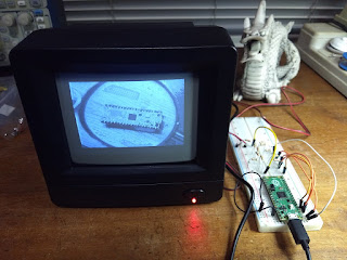
Generating Composite Video
One (of many) obvious differences between the Rapsberry Pi Pico and the other Raspberry Pi models is the lack of video output (remember, the Pi Pico is a microcontroller board and the others are single board computers).
Not a big problem! With a few resistors and some ingenious software we can generate video with the Pi Pico. My main interest in this is to build a serial terminal for my retro microprocessor boards (you can see my current effort at https://github.com/dquadros/RPTerm).
This experiment was done in April 21, based on an article by Dean Belfield. Since then he has improved his hardware and code in many ways, including adding color. Meanwhile I moved on to VGA video .
Composite video is very old (created in the middle 50s), but has survived to this day. It was created (originally) for transmitting monochrome video for CRTs (cathodic ray tubes). In a CRT we have an electron beam sweeping the screen, most of the time from left to right and top to bottom. At end of each horizontal line we have the horizontal retrace, where the beam is moved quickly from right to left. At the end of the screen we have the vertical retrace, where the beam returns to the top.
The basic composite video signal transmits the luminance (brightness) and marks where the horizontal and vertical retraces occur. To support color, the chrominance (color information) is modulated in a subcarrier. We are going to talk here about monochrome video only.
The aspect of the video signal is like this:
- Follow the indicated voltage levels. This will be done by resistive divisors.
- Generate various luminance levels, for a grayscale picture. This will be done by a DAC (digital analog converter) also made up from resistors.
- Follow the specified timings.
- Generate pixels fast enough to get a good horizontal resolution. The PIO and DMA will be used for this.
- Each line consists of 379 "pixels" instead of the 382 in the original code
- The left margin was reduced from 18 to 15 "pixels"
- In the line counting for composing a frame the margins where reduced: in the top from 63 to 42 lines and in the bottom from 50 to 21, making up the 50 line difference between PAL e NTSC
The resulting code can be seem in my github. The circuit used is the same as in the original article.


Comments
Post a Comment