Using the PIO to interface a HC-SR04 Ultrasonic Sensor
The more I get to know the PIO, the more opportunities to use it I see. This time the device to interface is the well known HC-SR04 ultrasonic sensor.
The HC-SR04 will send an ultrasonic signal when a 10 ms pulse is given to the trigger pin. After that, the echo pin will stay high until an echo is detected or 38 ms has passed. This time values come from a datasheet found in the internet, I also found code that uses different values.
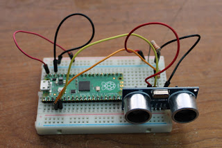
Before looking at the code, lets see how to connect the sensor to a Pi Pico. It's just four connections:
- Vcc: the datasheet specifies 5V. I found some examples using 3,3V but that did not work for me. As I am powering the Pi Pico from USB, a connect this pin to VBUS.
- GND: connect to any of the GND pins in the Pi Pico.
- Trigger: this is a TTL input, so can be connect to any GPIO pin in the Pi Pico. In my test I used GPIO3.
- Echo: another TTL signal, but it is an output. Powering the HC-SR04 with 5V, this pin will go above 3,3V and will damage the Pi Pico. I used a simple 22K / 33K resistor voltage divisor to connect to GPIO2.
The figure bellow shows the connections:
When programming in the Arduino IDE, we use the pulseIn() function to measure the echo pulse. Looking for MicroPython code in the internet, I found people using utime.ticks_us() in a loop. While the results are good, (1) it ties up the processor and (2) any interrupt while waiting can affect the result. Using the PIO we can do the measurement independent of the processor, we can also use it to generate the trigger pulse.
The first decision is what clock to use in the PIO. As we want to measure (with a good precision) a time between 150uS and 38ms, a half microsecond cycle (2MHz clock) is a good choice.
The PIO program is not complicated, but there are some PIO instructions peculiarities:
- A register can only the initialized with a value between 0 and 31. The initial counter value is got from the transmission queue and moved to the counting register ((PULL, MOV X,OSR).
- The WAIT instruction has no timeout. If no sensor is connected the program will stall waiting for echo to go high.
- The JMP instruction can only JMP on a high in a pin. As we are testing for a low, the code is a little strange.
- When using JMP for a loop, it will first (unconditionally) decrement the counter and then jump if the counter was not zero before the decrement. If the counter was zero it will not jump, but the counter will now be 2^32^-1. A little unusual, but works fine in our case.
The final PIO program receives (through the transmission queue) the timeout value (I used 300000 cycles, 150ms) and sends back (through the reception queue) the remaining counter. From this we calculate the number of cycles and microseconds for echo to go down. The distance is found remembering that the signal had to go and return and the speed of sound is 340m/s.
Here is the complete MicroPython program:
import utime
import rp2
from rp2 import PIO, asm_pio
from machine import Pin

# Program para o PIO
@asm_pio(set_init=rp2.PIO.OUT_LOW,autopush=False)
def ULTRA_PIO():
    # wait for a request
    pull()
    mov (x,osr)

    # generate trigger pulse: 10 us (20 ciclos)
    set(pins,1) [19]
    set(pins,0)

    # wait for the start of the echo pulse
    wait(1,pin,0)

    # wait for the end of the echo pulse
    # decrement X by 2 cicles (1us)
    label('wait_echo')
    jmp(pin,'continue')
    jmp('fim')
    label('continue')
    jmp(x_dec,'wait_echo')

    # retorn echo pulse duration
    label('fim')
    mov(isr,x)
    push()

trigger = Pin(3, Pin.OUT)
echo = Pin(2, Pin.IN)
sm = rp2.StateMachine(0)
while True:
    sm.init(ULTRA_PIO,freq=2000000,set_base=trigger,in_base=echo,jmp_pin=echo)
    sm.active(1)
    sm.put(300000)
    val = sm.get()
    sm.active(0)
    tempo = 300000 - val
    distance = (tempo * 0.0343) / 2
    print('Distance = {0:.1f} cm'.format(distance))
    utime.sleep_ms(1000)


Comments
Post a Comment